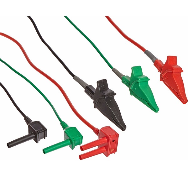
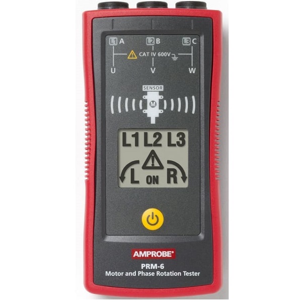
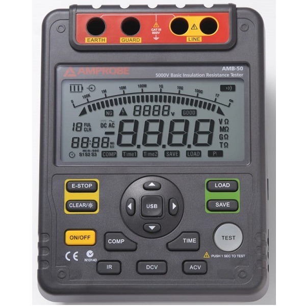
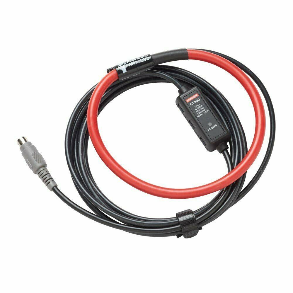
| Content | Use for Wire Tracer series AT-2000 | TEST LEAD SET FOR INSULATION RESISTANCE TESTERS | If you install or connect 3-phase motors and systems, you recognize the importance of verifying the correct motor rotation and wiring phase sequence. Improper connections can cause motors to rotate in reverse direction, potentially damaging the motor and the equipment it is powering. | The Amprobe AMB-50 High-Voltage Insulation Tester has the necessary features for professional insulation diagnostics. It features calculation of PI and DAR parameters. The pass/fail comparison function helps to improve testing productivity. Readings are clearly displayed on a large backlit LCD display. Windows compatible PC Software and USB communications port serve for connecting the instrument to the PC and management of the recorded test data. | Poor grounding is dangerous and contributes to unnecessary downtime and increases the risk of equipment failure. The Amprobe GP-2A Earth Ground Resistance Tester provides accurate and reliable measurements for ground resistance and soil resistivity to assure the safety and performance of an electrical system. The GP-2A is complete with PC software that allows the user to download critical recorded measurements and to create professional reports for customers. | Amprobe Flex Current Sensor Developed for the Amprobe DM-5, your all-in-one solution for excellent power quality. |
| Additional information |
| Weight |
1 lbs |
| Dimensions |
11.9 × 10 × 5.8 in |
|
|
| Weight |
1 lbs |
| Dimensions |
4 × 10 × 2 in |
|
| Weight |
6 lbs |
| Dimensions |
10 × 8 × 4.5 in |
|
| Weight |
2 lbs |
| Dimensions |
12.4 × 8.3 × 6.6 in |
|
| Weight |
2 lbs |
| Dimensions |
10 × 10 × 10 in |
|