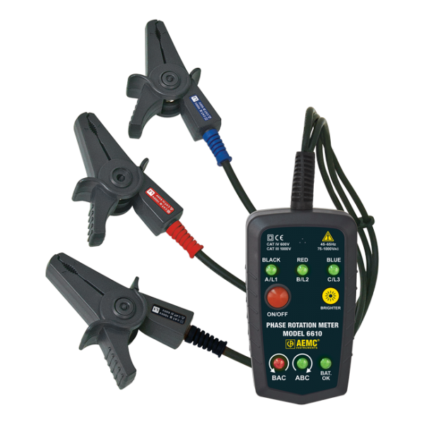
Phase Rotation Meter Model 6610 (Non-contact)
Available for Quote
The Phase Rotation Meter Model 6610 is an essential tool for any installation, inspection and maintenance facility. The Model 6610 is a phase meter with voltage sensing detector clips (no metal contact points) designed to identify phase rotation on 3-phase systems and identify live and open/de-energized phases. The phase order is determined as soon as the leads are connected. The presence of live wires and phase sequence are provided by LED indication and buzzer as soon as detection has occurred. The Model 6610 is ideal for installing rotating machinery or motors, and for checking generator phase rotation direction.
Quick Comparison
| Settings | Phase Rotation Meter Model 6610 (Non-contact) remove | AEMC 6527 4G Ohm, 250V/500V/1000V Digital Megohmmeter remove | Clamp-on Meter Model 670 (Dual Display, TRMS, AC Amps, AC/DC Volts, Ohms, Continuity, Frequency, & Temperature) remove | Digital FlexProbe Model 400D-10 w/6' Lead (TRMS, 4AAC, 40AAC, 400AAC) remove | Power Clamp-on Meter Model 205 (TRMS, 1000VAC/DC, 600AAC/900ADC, Ohms, Continuity, Phase Rotation, Power, THD) remove | Clamp-on Meter Model CM605 (100AAC/DC, Low Current) remove | ||||||||||||||||||||||||
|---|---|---|---|---|---|---|---|---|---|---|---|---|---|---|---|---|---|---|---|---|---|---|---|---|---|---|---|---|---|---|
| Image | |  | 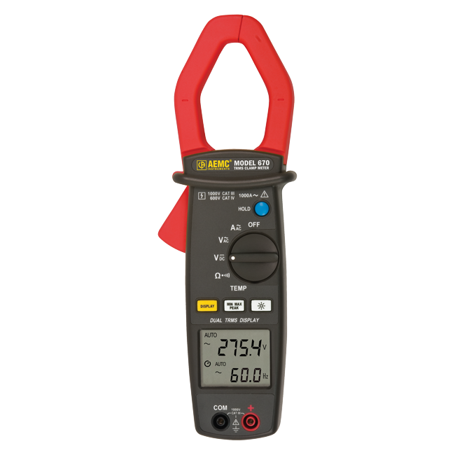 |  |  | 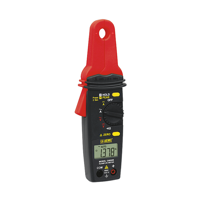 | ||||||||||||||||||||||||
| SKU | N_AEMC 6610 | N_AEMC 6527 | N_AEMC 670 | N_AEMC 400D-10 | N_AEMC 205 | N_AEMC CM605 | ||||||||||||||||||||||||
| Rating | ||||||||||||||||||||||||||||||
| Price | Available for Quote | Available for Quote | Available for Quote | Available for Quote | Available for Quote | Available for Quote | ||||||||||||||||||||||||
| Stock | ||||||||||||||||||||||||||||||
| Availability | ||||||||||||||||||||||||||||||
| Add to cart | ||||||||||||||||||||||||||||||
| Description | The Phase Rotation Meter Model 6610 is an essential tool for any installation, inspection and maintenance facility. The Model 6610 is a phase meter with voltage sensing detector clips (no metal contact points) designed to identify phase rotation on 3-phase systems and identify live and open/de-energized phases. The phase order is determined as soon as the leads are connected. The presence of live wires and phase sequence are provided by LED indication and buzzer as soon as detection has occurred. The Model 6610 is ideal for installing rotating machinery or motors, and for checking generator phase rotation direction. | The Clamp-on Meter Model 670 is a general purpose professional clamp-on meter offering a complete set of measurement ranges, AC current, AC and DC voltage, resistance, continuity with beeper, frequency from V or A, and temperature. It is in compliance with international safety and quality standards ensuring you have the most professional and reliable measuring tool. This meter is designed to measure and display amps and volts at the same time. It also is auto-ranging and provides the best measurement range and resolution for troubleshooting. | The Model CM605 is a versatile device that is capable of measuring both AC/DC voltage (up to 600V) and AC/DC current up to 100 Amps. It can also measure resistance up to 10k? and includes a continuity buzzer to assist in circuit verification. The Multifunction Clamp-on Meter Model CM605 is a good choice for both process and general industrial applications. It can detect milliamp process signals, as well as the higher currents up to 100A associated with general industrial monitoring and troubleshooting. For operator convenience, the Model CM605 can also hold the last reading in the display and capture the peak value at the time of the measurement. | |||||||||||||||||||||||||||
| Content | ||||||||||||||||||||||||||||||
| Weight | 6 | 2 | 9 | 6 | 9 | 9 | ||||||||||||||||||||||||
| Dimensions | 5 × 5 × 5 in | 10 × 5 × 5 in | 6 × 6 × 12 in | 6 × 6 × 12 in | 6 × 6 × 12 in | 6 × 6 × 12 in | ||||||||||||||||||||||||
| Additional information |
|
|
|
|
|
|