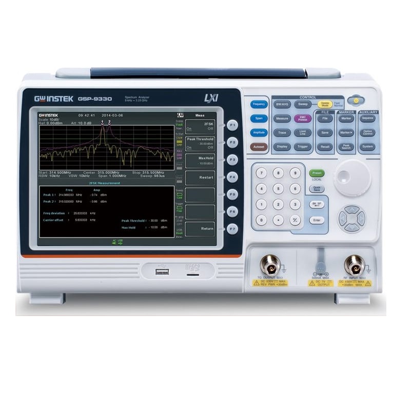
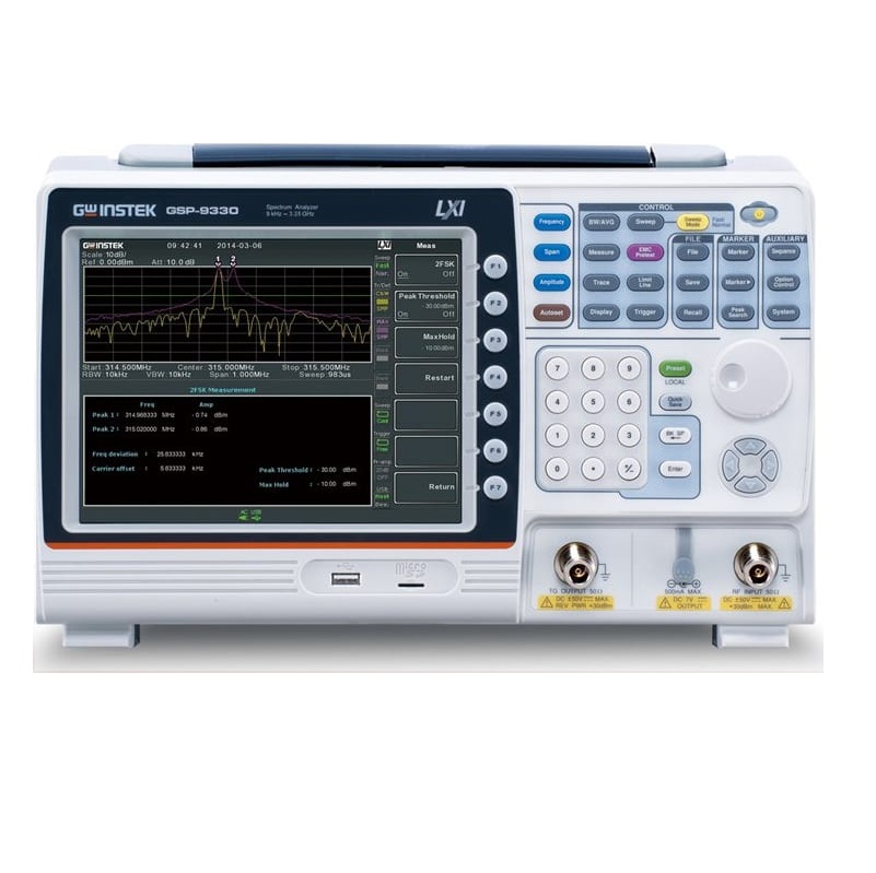
GSP-9330 Spectrum Analyzer
Features
- Frequency Range: 9kHz ~ 3.25GHz
- 0.025ppm Frequency Stability and 1ppm aging Rate
- RBW: 1Hz ~ 1MHz (3dB), 6dB EMI Filter: 200Hz, 9kHz, 120kHz, 1MHz
- Fastest sweep time: 204us
- Sensitivity: -149 dBm/Hz (@PreAmp on)
- Built-in Preamplifier, 50dB Attenuator, and Sequence Function
- Built-in EMC pretest function, Quasi-Peak/Average EMI detect mode
- Built-in 2FSK Analysis, AM/FM/ASK/FSK Demodulation & Analysis
- Built-in P1dB point, Harmonic, CHPW, OCBW, ACPR, SEM, TOI, CNR, CTB, CSO, N-dB bandwidth, Noise Marker, Frequency Counter, TDP, Gated Sweep
- Built-in Spectrogram, Topographic and Split-Window Display Modes
- Remote control EMI measurement software: SpectrumShot
TESTS MUST BE FAST!
The brand new GSP-9330, a high test speed spectrum analyzer with 3.25 GHz, provides the fastest 204 μs sweep speed. Users, via high speed sweep time, can easily handle and analyze modulation signals. The keys to handling modulated signals are fast sweep time and signal demodulation functions. In addition to the analog AM/FM demodulation and analysis function, GSP-9330 also provides digital signal ASK/FSK, and 2FSK demodulation and analysis capabilities. Nowadays, EMC issues are very crucial to product’s design processes. Therefore, GSP-9330 has incorporated the EMC pretest solution to facilitate EMC tests. The simple and easy EMC pretest procedures from GSP-9330 can tremendously shorten users’ product launch timeline.
GSP-9330 can meet customers’ EMC pretest requirements on the product development and verification stages. Users can detect and resolve problems at the early product development stage that can save time and money for product development and verification fee. As a result, users can expedite the process of products launch. GSP-9330 has the built-in EMI dedicated 200/9 k/120 k/1 MHz filter, 20 dB low noise amplifier and Quasi-Peak/Average detection mode to conduct radiation and conduction tests after collocating with the probe set.
GKT-008, the radiation test probe set, provides a complete near field test probe set to simplify the complex measurement procedures and to simulate 3m/10m far field tests from the labs. Using GKT-008 can greatly save engineers’ debugging time and the money for going back and forth to the labs. GKT-008 can collocate with the Tracking Generator function of GSP-9330 to conduct EMS pretests.
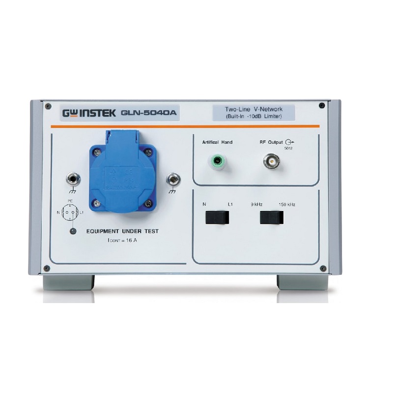
For conduction tests, GKT-008 can collocate with LISN and Isolated Transformer to conduct electromagnetic conduction tests. If users concern EUT’s large voltage variation or complexity, applying a Transient Limiter will make test equipment safer.
Manufacturer Specs
| General Specifications | |||
| Range | 9 kHz to 3.25 GHz | ||
| Resolution | 1 Hz | ||
| Frequency Reference | Accuracy | ±(period since last adjustment X aging rate) + stability over temperature + supply voltage stability | |
| Aging Rate | ±1 ppm max. | 1 year after last adjustment | |
| Frequency Stability over Temperature | ±0.025 ppm | 0 to 50 °C | |
| Supply Voltage Stability | ±0.02 ppm | ||
| Frequency Readout Accuracy | Start, Stop, Center, Marker | ±(marker frequency indication X frequency reference accuracy + 10% x RBW + frequency resolution) | |
| Trace points | Max 601 points, min 6 points | ||
| Marker Frequency Counter | Resolution | 1 Hz, 10 Hz, 100 Hz, 1 kHz | |
| Accuracy | ±(marker frequency indication X frequency reference accuracy + counter resolution) | RBW/Span >=0.02 ; Mkr level to DNL>30 dB | |
| Frequency Span | Range | 0 Hz (zero span), 100 Hz to 3.25 GHz | |
| Resolution | 1 Hz | ||
| Accuracy | ± frequency resolution1 | RBW: Auto; | |
| Phase Noise | Offset from Carrier | Fc =1 GHz; RBW = 1 kHz, VBW = 10 Hz; Average ≥ 40 | |
| 10 kHz | <-88 dBc/Hz | Typical | |
| 100 kHz | <-95 dBc/Hz | Typical | |
| 1 MHz | <-113 dBc/Hz | Typical | |
| Resolution Bandwidth (RBW) Filter | Filter Bandwidth | 1 Hz to 1 MHz in 1-3-10 sequence | -3dB bandwidth |
| 200 Hz, 9 kHz, 120 kHz, 1MHz | -6dB bandwidth | ||
| Accuracy | ± 8%, RBW = 1MHz | Nominal | |
| ± 5%, RBW < 1MHz | Nominal | ||
| Shape Factor | < 4.5:1 | Normal Bandwidth ratio: -60dB:-3dB | |
| Video Bandwidth (VBW) Filter | Filter Bandwidth | 1 Hz to 1 MHz in 1-3-10 sequence | -3dB bandwidth |
| Amplitude | |||
| Amplitude Range | Measurement Range | 100 kHz to 1 MHz | Displayed Average Noise Level (DANL) to 18 dBm |
| 1 MHz to 10 MHz | DANL to 21 dBm | ||
| 10 MHz to 3.25 GHz | DANL to 30 dBm | ||
| Attenuator | Input Attenuator Range | 0 to 50 dB, in 1 dB step | Auto or manual setup |
| Maximum Safe Input Level | Average Total Power | ≤ +33 dBm | Input attenuator |
| ≥10 dB | |||
| DC Voltage | ± 50 V | ||
| 1 dB Gain Compression | Total Power at 1st Mixer | > 0 dBm | Typical;Fc ≥ 50 MHz; preamp. off |
| Total Power at the Preamp | > -22 dBm | Typical;Fc ≥ 50 MHz; preamp. on | |
| mixer power level (dBm)= input power (dBm)-attenuation (dB) | |||
| Displayed Average Noise Level (DANL) | Preamp off | 0 dB attenuation; RF Input is terminated with a 50Ω load. RBW 10 Hz; VBW 10 Hz; span 500 Hz; reference level = -60dBm; trace average ≥ 40 | |
| 9 kHz to 100 kHz | < -93 dBm | Nominal | |
| 100 kHz to 1 MHz | < -90 dBm – 3 x (f/100 kHz) dB | ||
| 1 MHz to 2.7 GHz | < -122 dBm | ||
| 2.7 GHz to 3.25 GHz | < -116 dBm | ||
| Preamp on | 0 dB attenuation; RF Input is terminated with a 50Ω load ; RBW 10 Hz; VBW 10Hz; span 500 Hz; reference level = -60dBm; trace average ≥ 40 | ||
| 100 kHz to 1 MHz | < -108 dBm – 3 x (f/100 kHz) dB | Nominal | |
| 1 MHz to 10 MHz | < -142 dBm | ||
| 10 MHz to 3.25 GHz | < -142 dBm + 3 x (f/1 GHz) dB | ||
| Level Display Range | Scales | Log, Linear | |
| Units | dBm, dBmV, dBuV, V, W | ||
| Marker Level Readout | 0.01 dB | Log scale | |
| 0.01 % of reference level | Linear scale | ||
| Level Display Modes | Trace, Topographic, Spectrogram | Single / split Windows | |
| Number of Traces | 4 | ||
| Detector | Positive-peak, negative-peak, sample, normal, RMS(not Video), Average(EMI), Quasi-Peak(EMI) | Can be setup for each trace separately | |
| Trace Functions | Clear & Write, Max/Min Hold, View, Blank, Average | ||
| Absolute Amplitude Accuracy | Absolute Point | Center=160 MHz ; RBW 10 kHz; VBW 1 kHz; span 100 kHz; log scale; 1 dB/div; peak detector; 23°C±1°C; Signal at Reference Level | |
| Preamp off | ± 0.3 dB | Ref level 0 dBm; | |
| 10 dB RF attenuation | |||
| Preamp on | ± 0.4 dB | Ref level -30 dBm; | |
| 0 dB RF attenuation | |||
| Frequency Response | Preamp off | Attenuation: 10 dB; Reference: 160 MHz; 20 to 30°C | |
| 100 kHz to 2.0 GHz | ± 0.5 dB | ||
| 2GHz to 3.25 GHz | ± 0.7 dB | ||
| Preamp on | Attenuation: 0 dB; Reference: 160 MHz; 20 to 30°C | ||
| 1 MHz to 2 GHz | ± 0.6 dB | ||
| 2 GHz to 3.25 GHz | ± 0.8 dB | ||
| Attenuation Switching Uncertainty | Attenuator setting | 0 to 50 dB in 1 dB step | |
| Uncertainty | ± 0.25 dB | reference: 160 MHz, 10dB attenuation | |
| RBW Filter Switching Uncertainty | 1 Hz to 1 MHz | ± 0.25 dB | reference : 10 kHz RBW |
| Level Measurement Uncertainty | Overall Amplitude Accuracy | ± 1.5 dB | 20 to 30°C; frequency > 1 MHz; Signal input 0 to -50 dBm; Reference level 0 to -50 dBm; |
| Input attenuation 10 dB; | |||
| RBW 1 kHz; VBW 1 kHz; after cal; Preamp Off | |||
| ± 0.5 dB | Typical | ||
| Spurious Response | Second Harmonic Intercept | Preamp off; signal input -30dBm; 0 dB attenuation | |
| +35 dBm | Typical; 10 MHz < fc < 775 MHz | ||
| +60 dBm | Typical; 775 MHz ≤ fc < 1.625 GHz | ||
| Third-order Intercept | Preamp off; signal input -30dBm; 0 dB attenuation | ||
| > 1dBm | 300 MHz to 3.25 GHz | ||
| Input Related Spurious | < -60 dBc | Input signal level -30 dBm, Att. | |
| Mode, Att=0dB; 20-30ºC | |||
| Residual Response (inherent) | <-90 dBm | Input terminated; 0 dB attenuation; Preamp off | |
| Sweep | |||
| Sweep Time | Range | 204 us to 1000 s | Span > 0 Hz |
| 50 us to 1000 s | Span = 0 Hz; Min Resolution = 10 us | ||
| Sweep Mode | Continuous; Single | ||
| Trigger Source | Free run; Video; External | ||
| Trigger Slope | Positive or negative edge | ||
| RF Preamplifier | |||
| Frequency Range | 1 MHz to 3.25 GHz | ||
| Gain | 18 dB | Nominal | |
| (installed as standard) | |||
| Front Panel Input/Output | |||
| RF Input | Connector Type | N-type female | |
| Impedance | 50 ohm | Nominal | |
| VSWR | <1.6 :1 | 300 kHz to 3.25 GHz; Input attenuator ≥ 10 dB | |
| Power for Option | Connector Type | SMB male | |
| Voltage/Current | DC +7V / 500 mA max | With short-circuit protection | |
| USB Host | Connector Type | A plug | |
| Protocol | Version 2.0 | Supports Full/High/Low speed | |
| MicroSD Socket | Protocol | SD 1.1 | |
| Supported Cards | microSD, microSDHC | Up to 32GB capacity | |
| Rear Panel Input/Output | |||
| Reference Output | Connector Type | BNC female | |
| Output Frequency | 10 MHz | Nominal | |
| Output Amplitude | 3.3V CMOS | ||
| Output Impedance | 50 ohm | ||
| Reference Input | Connector Type | BNC female | |
| Input Reference Frequency | 10 MHz | ||
| Input Amplitude | -5 dBm to +10 dBm | ||
| Frequency Lock Range | Within ± 5 ppm of the input reference frequency | ||
| Alarm Output | Connector Type | BNC female | Open-collector |
| Trigger Input/ Gated Sweep Input | Connector Type | BNC female | |
| Input Amplitude | 3.3V CMOS | ||
| Switch | Auto selection by function | ||
| LAN TCP/IP Interface | Connector Type | RJ-45 | |
| Base | 10Base-T; 100Base-Tx; Auto-MDIX | ||
| USB Device | Connector Type | B plug | For remote control only; supports USB TMC |
| Protocol | Version 2.0 | Supports Full/High/Low | |
| speed | |||
| IF Output | Connector Type | SMA female | |
| Impedance | 50 ohm | Nominal | |
| IF Frequency | 886 MHz | Nominal | |
| Output level | -25 dBm | 10 dB attenuation; RF input: 0 dBm @ 1 GHz | |
| Earphone Output | Connector Type | 3.5mm stereo jack, wired for mono operation | |
| Video Output | Connector Type | DVI-I ( integrated analog and digital) , Single Link. Compatible with VGA or HDMI standard through adapter | |
| RS232 Interface | Connector Type | D-sub 9-pin female | Tx,Rx,RTS,CTS |
| GPIB Interface (Optional) | Connector Type | IEEE-488 bus connector | |
| AC Power Input | Power Source | AC 100 V to 240 V, 50 / 60 Hz | |
| Auto range selection | |||
| Battery Pack (Optional) | Battery pack | 6 cells, Li-Ion rechargeable, 3S2P | With UN38.3 Certification |
| Voltage | DC 10.8 V | ||
| Capacity | 5200 mAh / 56Wh | ||
| General | |||
| Internal Data storage | 16 MB nominal | ||
| Power Consumption | <65 W | ||
| Warm-up Time | < 30 minutes | ||
| Temperature Range | +5 °C to +45 °C | Operating | |
| -20 °C to + 70 °C | Storage | ||
| Weight | 4.5 kg (9.9 lb) | Inc. all options (Basic+TG+GPIB+Battery) | |
| Dimensions | 210 x 350 x 100 (mm) | Approximately | |
| 8.3 x 13.8 x 3.9 (in) | |||
| Tracking Generator (Optional) | |||
| Frequency Range | 100 kHz to 3.25 GHz | ||
| Output Power | -50 dBm to 0 dBm in 0.5 dB steps | ||
| Absolute Accuracy | ± 0.5 dB | @160 MHz, -10 dBm, Source attenuation 10 dB, 20 to 30°C | |
| Output Flatness | Referenced to 160 MHz, -10 dBm | ||
| 100 kHz to 2 GHz | ± 1.5 dB | ||
| 2 GHz to 3.25 GHz | ± 2 dB | ||
| Output Level Switching Uncertainty | ± 0.8 dB | Referenced to -10 dBm | |
| Harmonics | < -30 dBc | Typical, output level = -10 dBm | |
| Reverse Power | +30 dBm max. | ||
| Connector type | N-type female | ||
| Impedance | 50 ohm | Nominal | |
| Output VSWR | < 1.6:1 | 300 kHz to 3.25 GHz, source attenuation ≥ 12 dB | |
Tech Specs
Spectrum Analyzers/Spectrum Analyzers Template | |
|---|---|
| Bandwidth Range Max | 3.25 GHz |
| Bandwith Range Min | 9 kHz |
| Noise Floor | -139 dBm (-139 dB) |
| Tracking Generator | No |
| Type(Spectrum Analyzers) | Benchtop |
| Channel Power Measurement | Yes |
| Marker Measurement | Yes |
| Preamplifier | Yes |
| AM/FM Demodulation | Yes |
| Power Meter | No |
Test Equipment General Attributes | |
| Unique Features | Fast Sweep speed 204us Standard configurations supports: Modulation signal analysis for digital signals 2FSK, FSK, ASK, and analog signals AM, FM. Complete EMC Pretest Solution with: EMI detect mode: Quasi-peak, Average EMI filter (-6dB): 200Hz, 9KHz, 120KHz, 1MHz Dedicated EMC Function key. RBW range 1Hz-1Mhz in 1-3-10 sequence Signal Channel Analysis provides Channel Power, OCBW, ACPR, N-dB Bandwidth, SEM CATV parameter tests focus on CNR, CSO, and CTB parameters Signal Source’s stability characteristics can be tested via Phase Noise and Phase Jitter. Component or System’s linearity can be confirmed by TOI and P1dB Functions. Other measurements included: Harmonic, Frequency counter, Time Domain Power, and Gated Sweep Built in Spectrogram, Topographic and Split-window Display modes. Complementary remote control EMI measurement SW: SpectrumShot |
Standard Accessories
Power Cord, Certificate of Calibration,
CD-ROM (with Quick Start Guide, User Manual, Programming Manual, SpectrumShot Software, SpectrumShot Guide & IVI Driver)
Options
Option 01, Tracking Generator
Option 02,BatteryPack
Option 03, GPIB Interface
Optional Accessories
GSC-009, Soft Carrying Case
GRA-415, Rack Adapter Panel
Free Download
SpectrumShot PC Software for Windows System (available on GW Instek website)
IVI Driver Supports LabVIEW/LabWindows/CVI Programming (available on NI website)


